Screen-by-screen build document. Every asset is a real capture; every quoted line is verbatim from the session tape with its timecode. Anything authored is flagged.
Two halves. First, what laser welder setup is and what the learner will be able to do by the end. Then the cell from dead to ready — five hardware actions and two panel actions, on different parts of the machine, in an order that matters.
The framing to teach it with
Tyler, 7/06 00:02:58: “That’s the neat thing about the laser welder — a lot of this stuff is just like it’s a big equation, and they need to figure out what the variables are in that equation. For a lot of them it’s just two: you got the ID, you got the OD.” That is the mental model the overview installs, and it holds for nearly every module after: two offsets, two diameters, two passes.
Assessed
No — procedural
Screens
11
Assets
10 photographs, 1 clip all existing
To author
Lateral step track Recap composite
Source of truth
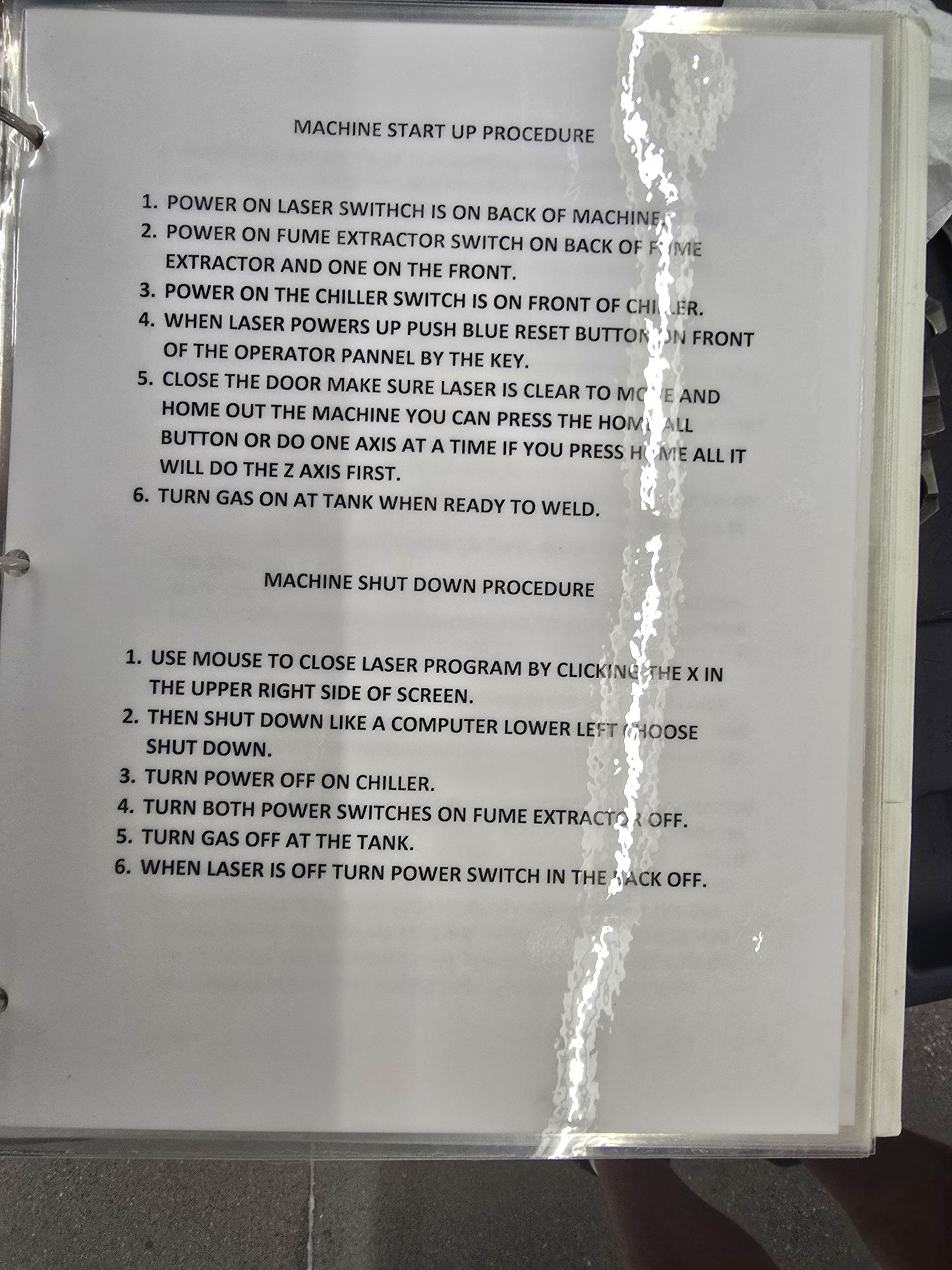
SME’s laminated page 20260616_131612
Why this module isn’t assessed
Tyler, 9 September: “I don’t think anything’s really being assessed here. It’s more just procedural, making sure they know those steps. And what the steps are for.”
That departs from the blueprint, which expects every module to check something — and it is defensible. Start-up isn’t in the signed twelve at all, and Mike’s own binder keeps MACHINE START UP PROCEDURE on a separate page from MACHINE SET-UP PROCEDURE. The shop treats them as different things; so does the course.
7/06 00:45:42“Is this something they might need to know? If they’re starting the machine.”
7/06 00:45:46“Yep. They need to know this process.”
Tyler Rydman, then Mike DeGraw — the exchange that put this module in the course.
Source of truth
20260616_131612.jpg · Mike DeGraw’s binder, 16 June
Six steps, transcribed verbatim — his spelling kept, because the course should use his words where it can.
POWER ON LASER SWITHCH IS ON BACK OF MACHINE.
POWER ON FUME EXTRACTOR SWITCH ON BACK OF FUME EXTRACTOR AND ONE ON THE FRONT.
POWER ON THE CHILLER SWITCH IS ON FRONT OF CHILLER.
WHEN LASER POWERS UP PUSH BLUE RESET BUTTON ON FRONT OF THE OPERATOR PANNEL BY THE KEY.
CLOSE THE DOOR MAKE SURE LASER IS CLEAR TO MOVE AND HOME OUT THE MACHINE — YOU CAN PRESS THE HOME ALL BUTTON OR DO ONE AXIS AT A TIME — IF YOU PRESS HOME ALL IT WILL DO THE Z AXIS FIRST.
TURN GAS ON AT TANK WHEN READY TO WELD.
Four devices, five hardware actions
Step 2 is two switches — one on the back of the extractor, one on the front. Both are photographed, and both are required. That asymmetry is the only place in start-up where doing half the job looks identical to doing all of it.
Screen sequence
Nine screens. Every hardware screen runs the same three beats — the need, then the control, then the state change. Purpose first, mechanism second.
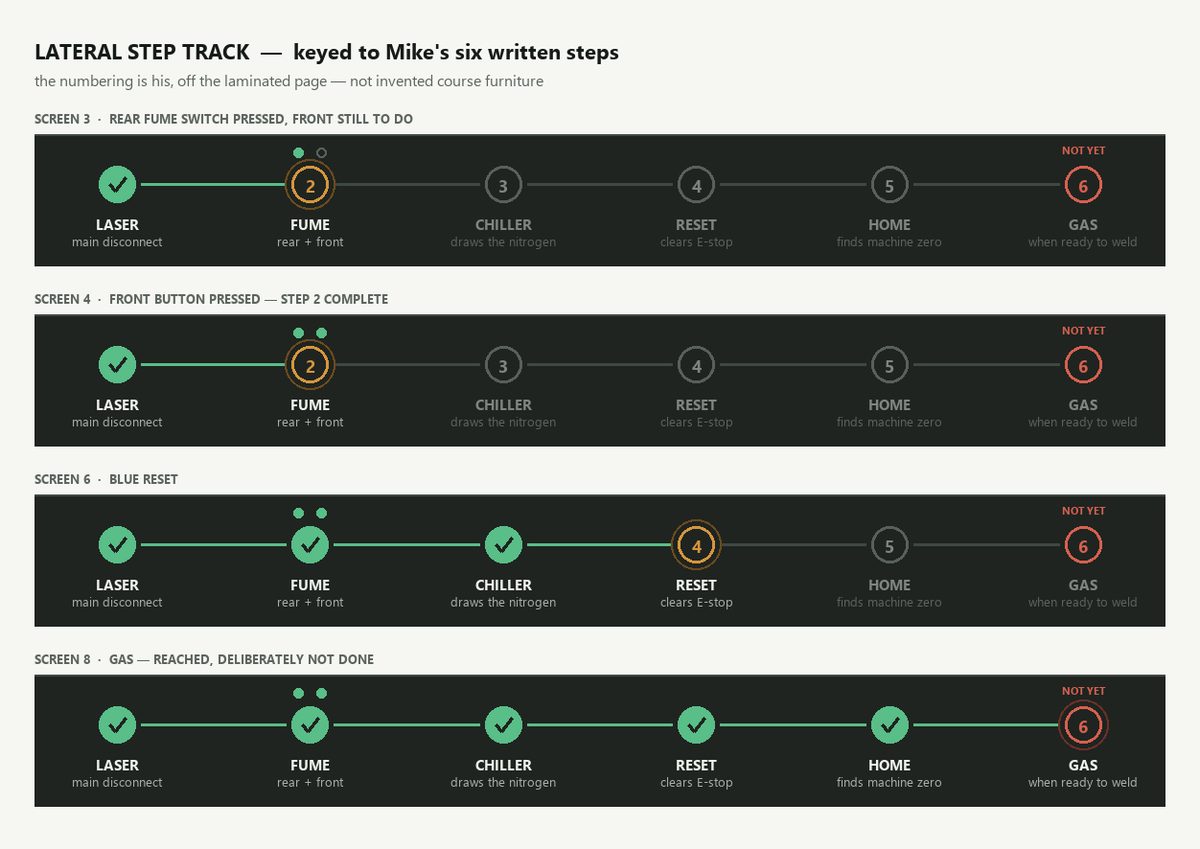
A persistent lateral step track runs along the bottom of every screen, with six nodes matching the six lines on Mike’s laminated page. The numbering is his, not ours — a learner who sees this and then walks up to the real binder is looking at the same list with the same numbers.
The track at four points in the module — note step 2’s two sub-dots, and step 6 sitting red throughout
Three things it does that a plain progress bar would not. Step 2 carries two sub-dots — one fills on the rear rocker, the other on the front button, and the node does not tick until both are in, so the two-switch trap becomes something the learner watches fail to complete rather than a warning they might skip. Step 6 sits red and marked NOT YET from screen 1 onward, so the whole module is spent looking at a step that must be left alone. And the completed nodes echo the HMI rather than inventing status language.
The course in one page — composite to author
01
What setup is
SaysSetup is everything between a job arriving and the first good weld. Twelve modules, one job, start to finish.
DoesContinue.
7/06 00:02:58“That’s the neat thing about the laser welder — a lot of this stuff is just like it’s a big equation, and they need to figure out what the variables are in that equation. For a lot of them it’s just two: you got the ID, you got the OD.”
The mental model to install here. It holds for nearly every module after — two offsets, two diameters, two passes.
The eight course-level objectives, in Tyler’s words on 7/06 00:01:06–00:04:45:
1
Interpret the setup documentation — “the part number, the fixture number that’s going to hold it, the offset, jaws and masters, the ID and the OD weld size, the diameter, the feed, the gas pressure”
2
Position the machine for setup verification — X/Y/Z and rotary chuck, for laser camera and nozzle access
3
Use dry run, cycle stop, beam axis and offsets correctly; stop at the setup check position
4
Make small beam axis adjustments — “that’s where they actually look at the screen… they’re looking at the clarity”
5
Teach G50 and G51
6
Verify through dry run — “the ID first, then we move up and do the OD… we’ll run them both and then we’ll position the nozzle”
7
Position support systems and confirm readiness
8
Judge the first weld — “decide whether to proceed, retry, troubleshoot, or ask you or the shop floor manager if you’re not here, or another SME slash supervisor”
Objective 8 settles an open question
The four-way decision — proceed, retry, troubleshoot, escalate — is in Tyler’s own words on tape at 00:04:32, with its targets named. Escalation is in, and Modules 11 and 12 carry it.
Explicitly out of scope, from the same stretch
Fume extraction positioning. Tyler asks whether the hose position matters for setup; Mike, 00:04:12: “No, that’s just sucking off… that’s not something that they’d have to worry about for setup.” Powering the extractor on IS in scope — it is start-up step 2. Aiming it is not.
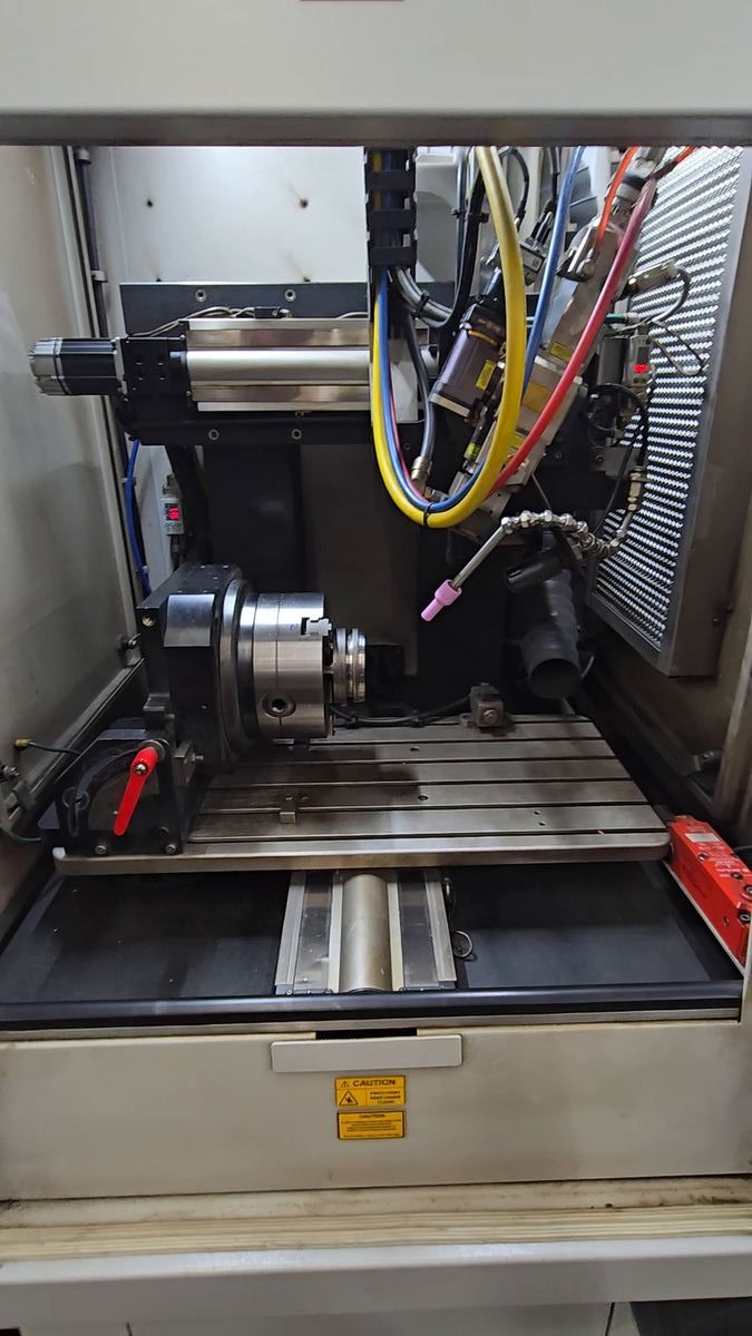
20260706_095157.mp4 at 1.6 s — the clearest unobstructed view of the work envelope in the project
02
Starting the machine
SeesThe work envelope, door open, nothing running.
SaysStarting the machine is one procedure with six steps. The switches for it sit in different places on and around the machine — and several of them look the same.
DoesContinue.
7/06 00:45:29“That’s just how you start the machine.”
7/06 00:40:03“And then another one of these switches.” 00:40:09“Same thing.”
Mike DeGraw. He never counts machines — it is the machine, and a family of similar switches.
Where the switches are — locations quoted from his written page
Step
The switch
Where
Turns on
1
Rotary disconnect, red handle
ON BACK OF MACHINE
the laser
2
Illuminated I/O rocker
ON BACK OF FUME EXTRACTOR
the extractor — mains
2
Round power button
AND ONE ON THE FRONT
the extractor — runs it
3
Rotary disconnect
ON FRONT OF CHILLER
the chiller, which draws the nitrogen
4
Blue R / RESET
ON FRONT OF THE OPERATOR PANNEL BY THE KEY
clears the emergency stop
Steps 5 and 6 are not switches
Step 5 is All Home, a button on the screen. Step 6 is the valve at the gas tank, and it is deliberately not done at start-up. Four physical switches, five actions — because step 2 is two of them.
Framing
Start-up is its own procedure, separate from setting up a job. Mike keeps them on separate pages in his binder; the course keeps them as separate halves of this module.
20260706_094256.jpg · 20260706_094308.jpg
03
Laser main power
The needThe laser is the machine, and it is the slowest thing to wake. It goes first so it can boot while you do everything else.
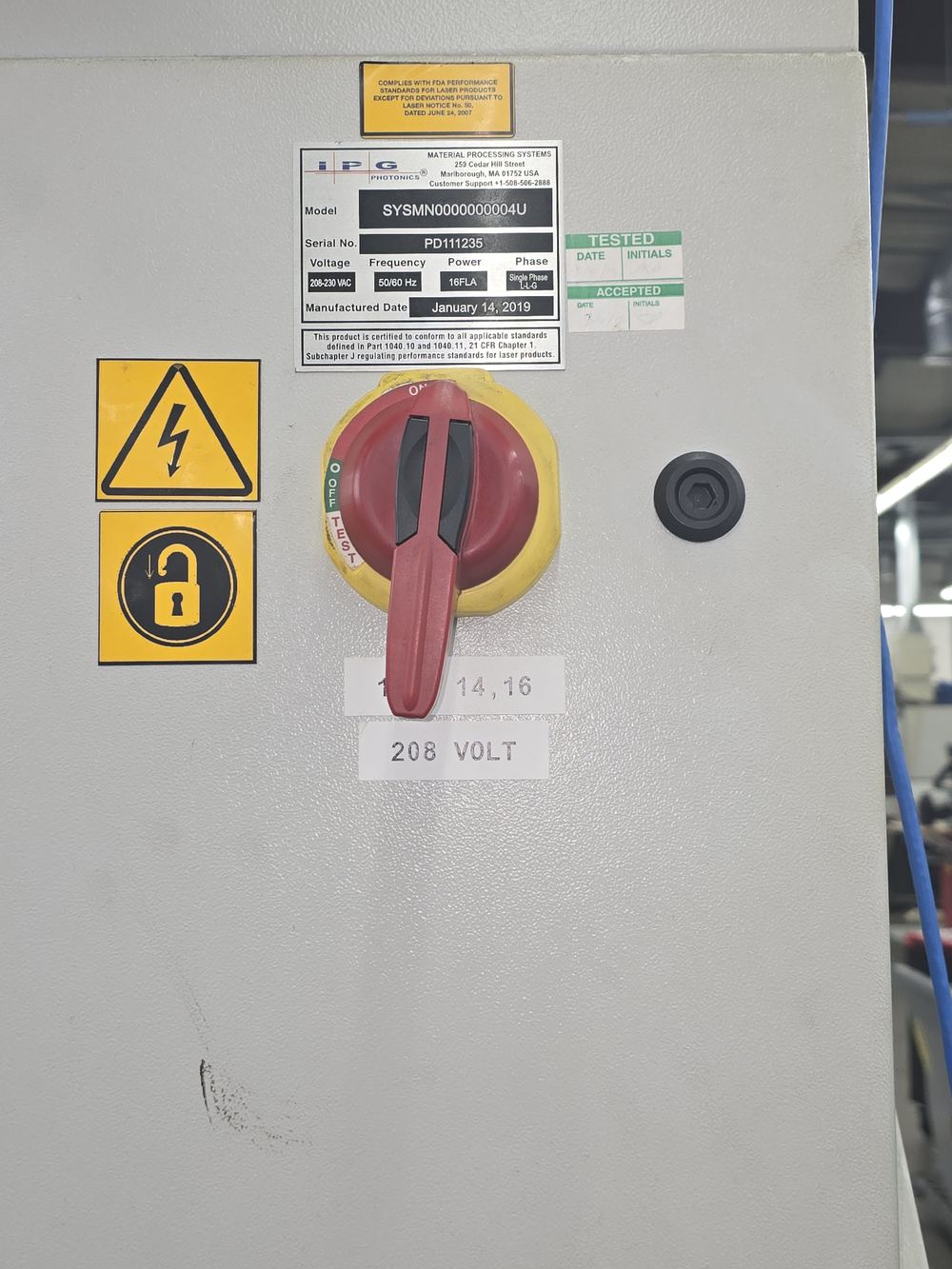
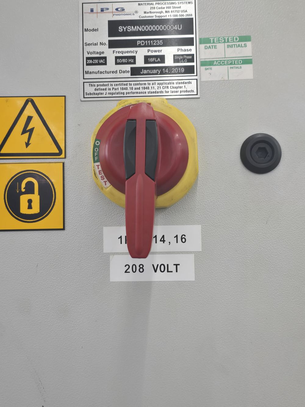
The controlRotary disconnect on the back of the machine cabinet — red handle, yellow plate.
The changeHandle rotates clockwise; the frame swaps to the close view.
7/06 00:39:34“So when it’s off, this tail will be over here.”
7/06 00:39:37“So you turn it clockwise.”
Callout
The tail of the handle points one way when off and the other when on. That is how you read the state from across the cell without walking round the back.
20260706_094315.jpg
04
Fume extraction — rear switch
The needWelding makes a plume. The extractor pulls it off the weld before it settles on the optics — or on the operator.
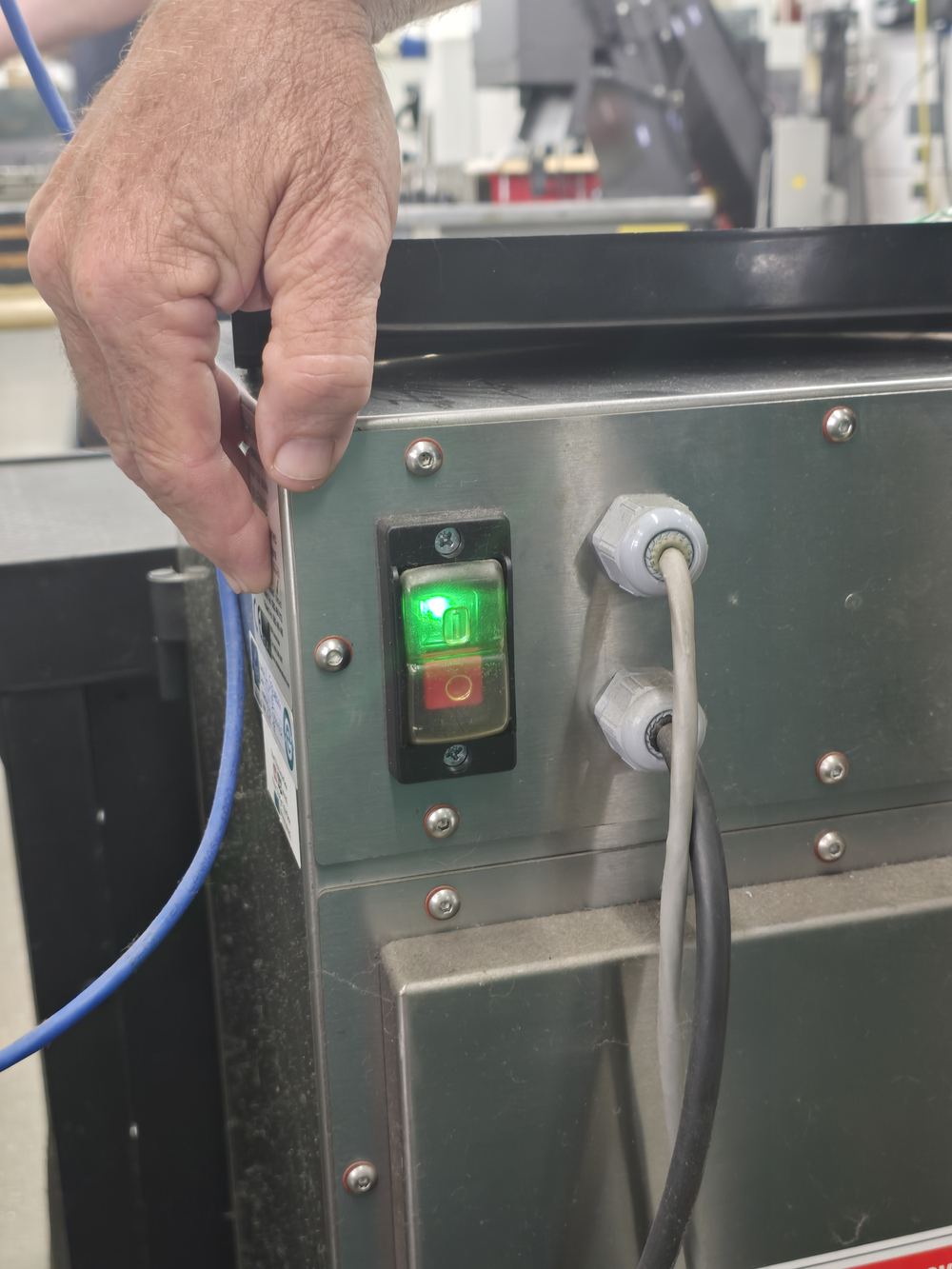
The controlIlluminated rocker on the stainless side panel. Green I lights when on.
The changeRocker illuminates green.
7/06 00:39:43“Press this button right here to turn this on.”
7/06 00:39:48“So you press that top button.”
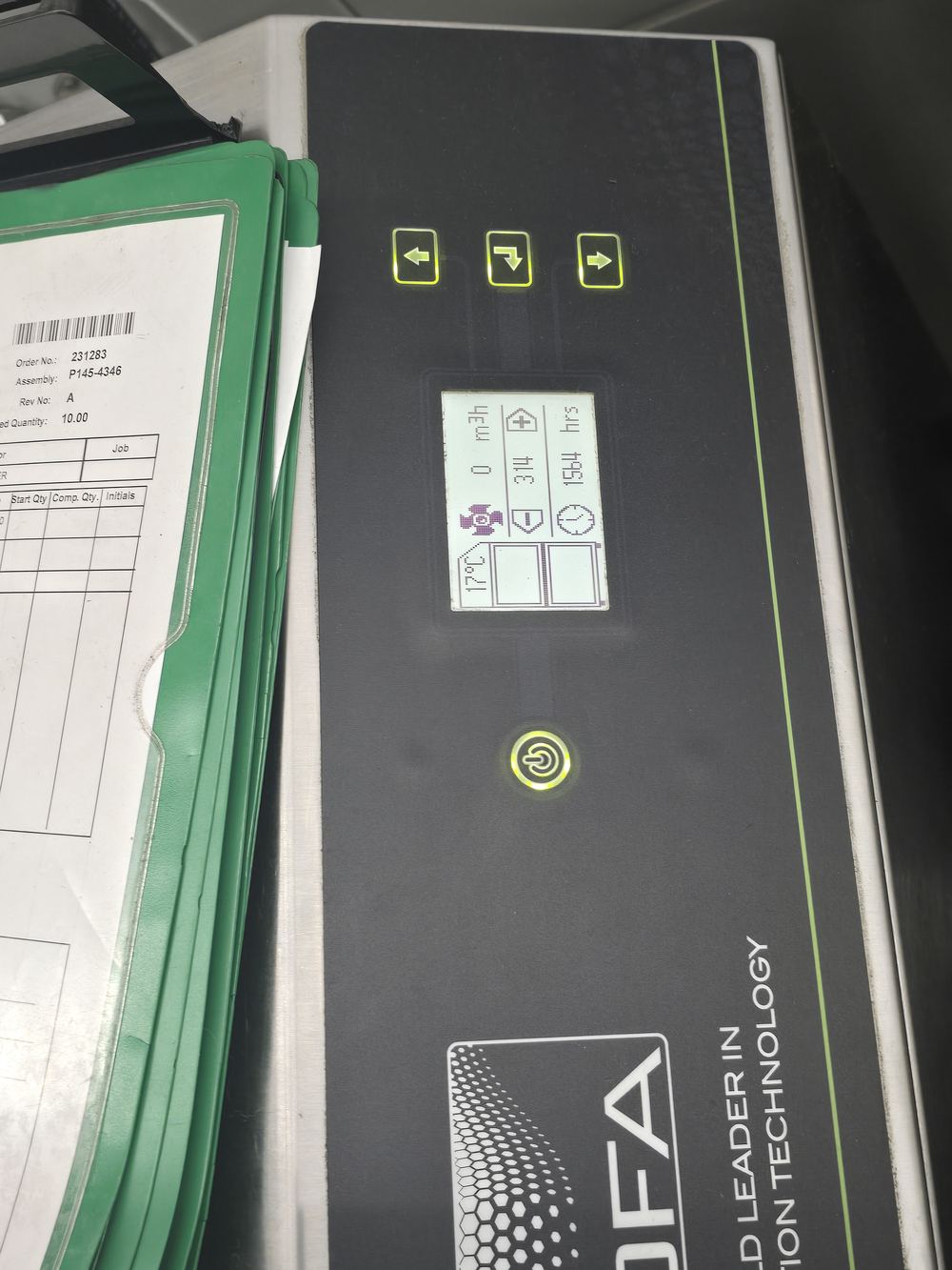
20260706_094327.jpg — the only BOFA front-panel frame in the project
05
Fume extraction — front button
The needThe rear switch is mains power to the cabinet. The front button actually starts the unit. Both are required.
And at the endIt goes off when the machine goes off — on at start-up, off at shut-down. It is not switched per job.
The controlRound power button on the BOFA front panel. Red when off, green when running.
The changeRed → green.
7/06 00:39:51“And you touch the round one.”
7/06 00:39:55“It’ll be red. You touch it and it’ll make it green.”
The trap
Mike’s written step 2 says it in one line: SWITCH ON BACK OF FUME EXTRACTOR AND ONE ON THE FRONT. Power at the back with no start at the front means no extraction — and nothing on the HMI will tell you.
20260706_094338.jpg
06
Chiller
The needThe chiller is what draws nitrogen from the tank. It is one half of a two-part gas system: the chiller pulls the feed, the tank valve opens the source. Both are required, and they sit at opposite ends of this procedure — step 3 and step 6.
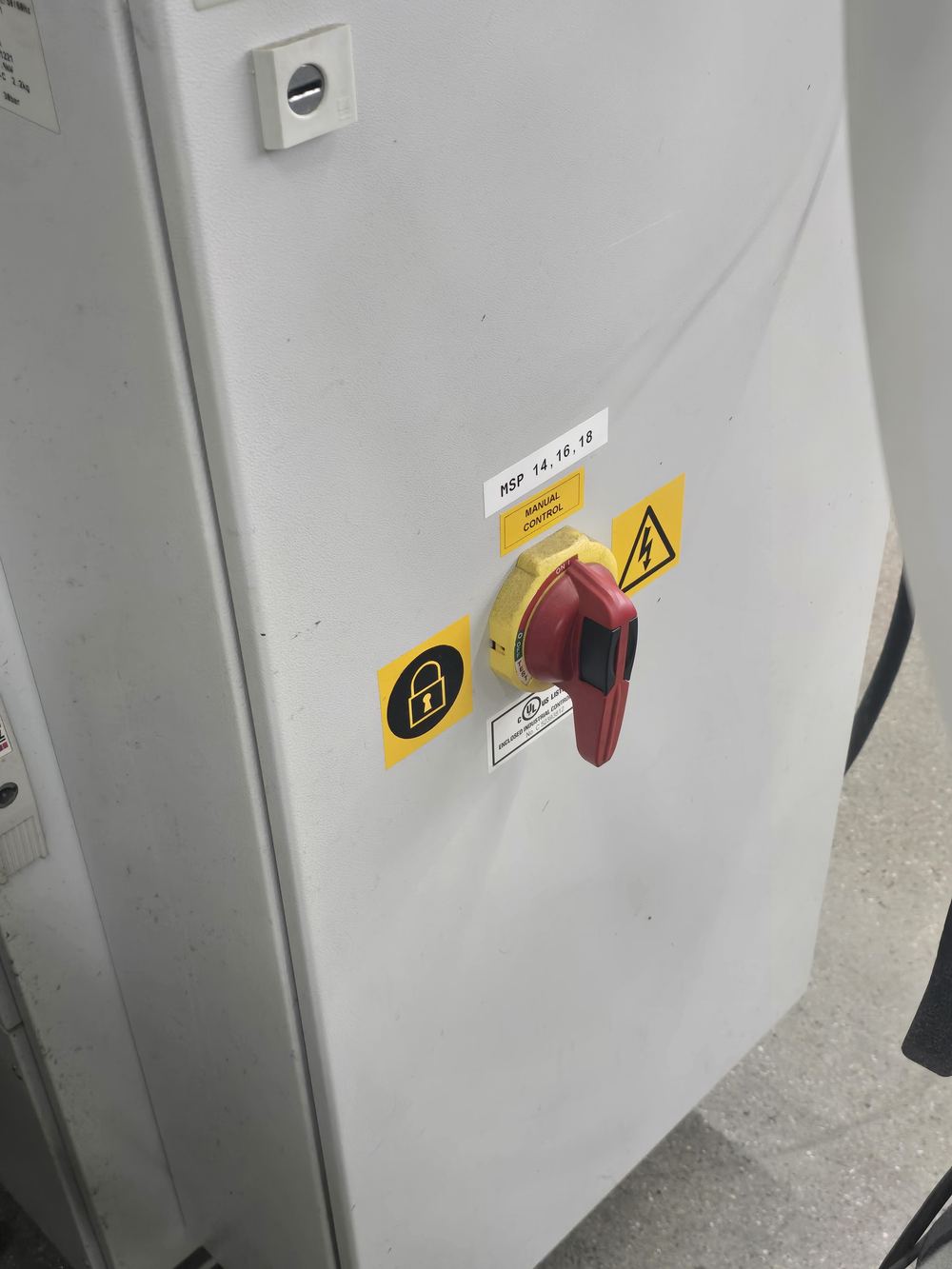
The controlA second rotary disconnect, same pattern as the laser’s, on the white floor cabinet. Labelled MSP 14, 16, 18.
The changeHandle clockwise. All four devices now green — but MACHINE stays amber.
7/06 00:40:03“And then another one of these switches.”
7/06 00:40:09“Same thing. Turn it clockwise to turn it on.”
Half of a pair — the other half is screen 8
Turning the chiller on does not give you gas, and opening the tank does not either. You need both. They are three steps apart on the written page, which is exactly how a learner ends up with one of them and no nitrogen at the nozzle. Tyler Rydman, 9 September — not on tape; the chiller is never spoken about in 167 minutes.
Then it waits
The touch panel PC boots on its own and takes its time — 00:40:15“Starting window.”00:40:16“Takes its time.” There is nothing to do but wait, and the module should say so rather than leave the learner hunting for a next click.
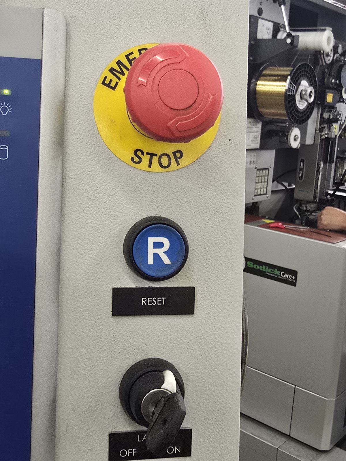
20260706_094846.jpg — the button itself. The column runs top to bottom: EMERGENCY STOP, the blue R with its RESET legend, then the LASER OFF/ON key.
07
Blue RESET
The needThe machine comes up in emergency-stop state by design. It will not move until you clear it, and clearing it is a deliberate act.
The controlBlue RESET on the operator column, beside the key switch.
The changeRed bar clears; MACHINE, LASER and HEAD go green.
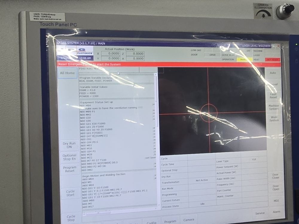
20260706_094850.jpg — the state the button clears
7/06 00:45:07“So to finish the startup, you have to press this blue button.”
7/06 00:45:29“That’s just how you start the machine. You got to hit that.”
Not the key
The LASER OFF/ON key switch sits right beside the blue button and is not part of start-up. 094846 shows the key already at ON; four seconds later 094850 still reads HEAD = NOT READY with the E-stop bar up. The key is a standing plant enable. What clears the banner is RESET.
Two things called Reset — only one starts the machine
This one is physical, on the operator column between the E-stop and the key. The HMI’s left rail also carries a soft button labelled Program Reset, which resets the loaded program to the top and has nothing to do with start-up. The banner is the tell: Reset Emergency Stop to start the System asks for the E-stop chain to be cleared, and that is cleared at the panel, not on the screen. Worth building as a distractor.
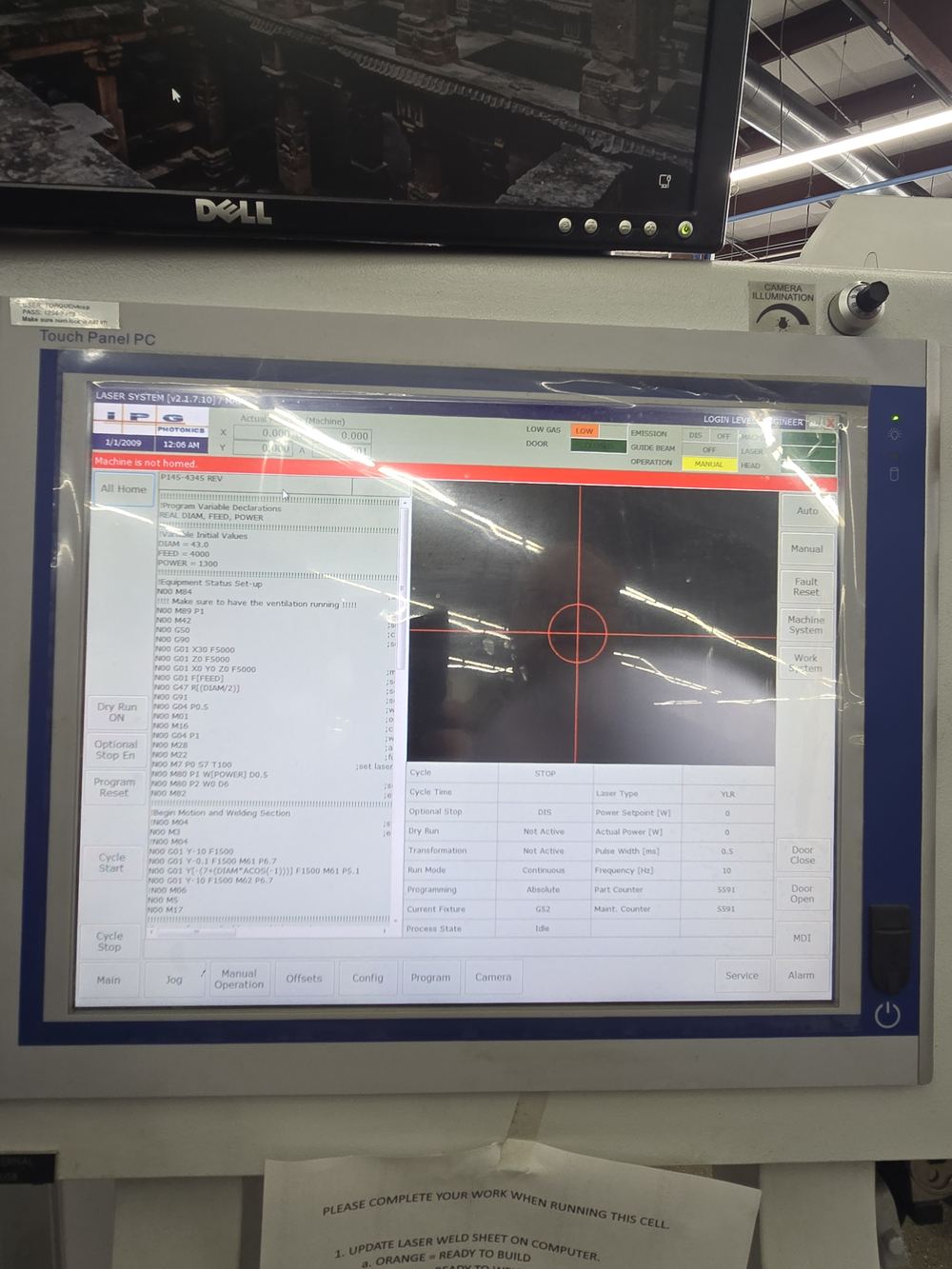
The needThe machine has no idea where its axes are until it finds its own zero. Until then it refuses to run a program.
The controlAll Home, top of the HMI’s left rail. The red bar now reads Machine is not homed.
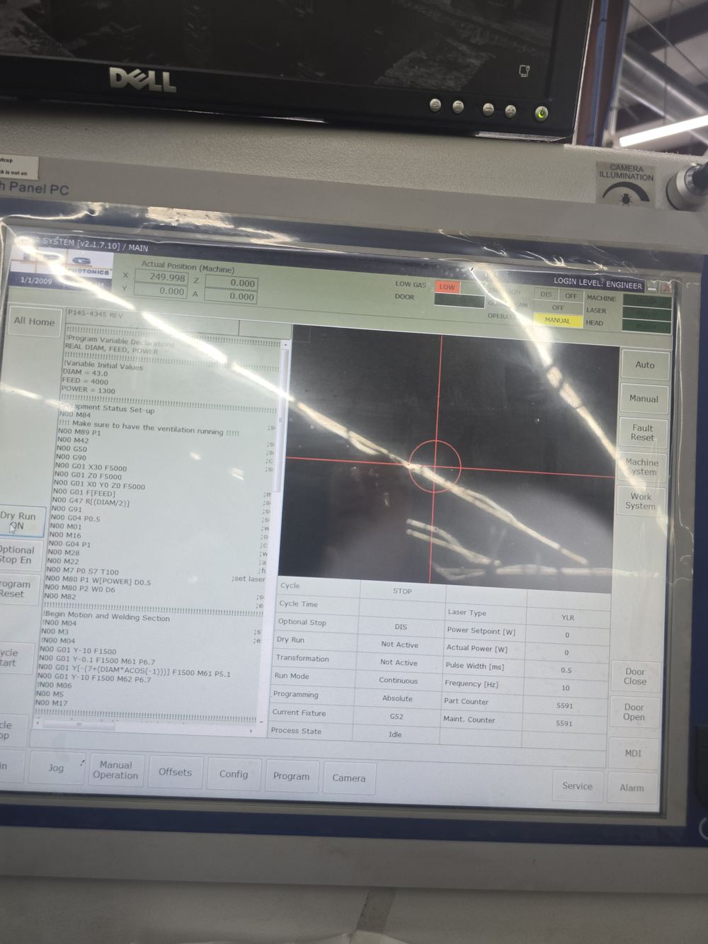
The changeAxes travel; bar clears; Actual Position reads X 249.998 / Y 0.000 / Z 0.000 / A 0.000.
7/06 00:45:33“And then it’ll say the machine is not home. So you have to home it.”
7/06 00:45:49“So then you hit the all home button. And then these will all start moving.”
7/06 00:46:17“It moves them all to the home position.”
Two details from the written page
Door closed first, and check the head is clear to move. And Z homes first — deliberate, because it lifts the head out of the way before anything traverses.
20260706_095027.jpg → 095029.jpg · clip 20260706_095157.mp4 — the run itself
09
The first dry run — with nothing on the fixture
The needHoming parks the axes at machine zero. The head has to come back in from there, and the path it takes is not the path it takes in normal running.
The controlDry Run — it lights yellow — then Cycle Start.
The ruleNothing on the fixture. Not the part, not the fixture if it is already loaded — an empty envelope.
7/06 00:46:30“So what I do is, to get it back into position, I do a dry run… without a part on.”
7/06 00:47:00“For the first dry run, because I want to get the machine where it belongs. Because of the way it travels in from home. Because it would hit the part and bump your nozzle.”
7/06 00:47:42“So the initial dry run on machine start-up is without a part.”
Why this earns a screen of its own
It is the only start-up step with a cost attached. Do it with a part loaded and you bump the nitrogen nozzle — the one thing that takes twenty minutes to position and that Mike calls “usually the biggest problem” (6/16 00:07:41). The learner is not being asked to be tidy; they are protecting later work.
Once per power-up, not once per job
7/06 00:47:17“And you only need to do that when you first start it up.” Every later dry run in this course — and there are many — runs with the part loaded. This one is the exception.
Open — which program is loaded
No program is selected between homing and Cycle Start; the panel simply holds whatever was last used. Whether that matters is question 7 on Mike’s list. Taught as written, which is what the tape shows.
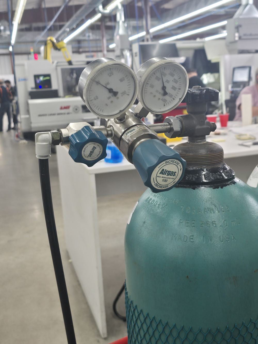
20260706_095810.jpg · 20260706_095819.jpg
10
Gas — on the list, but not yet
The needNitrogen shields the weld. But it is bottled gas, and it is not needed until the moment you actually weld.
SaysThis is step 6, and you don’t do it now.
DoesContinue.
written step 6“TURN GAS ON AT TANK WHEN READY TO WELD.”
written shut-down 5“TURN GAS OFF AT THE TANK.”
What is inside the part — and why the gas matters
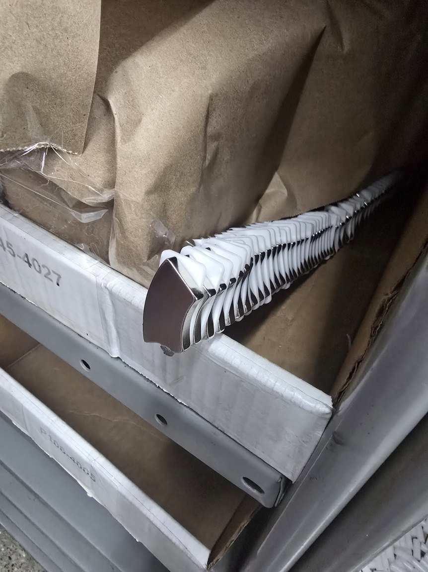
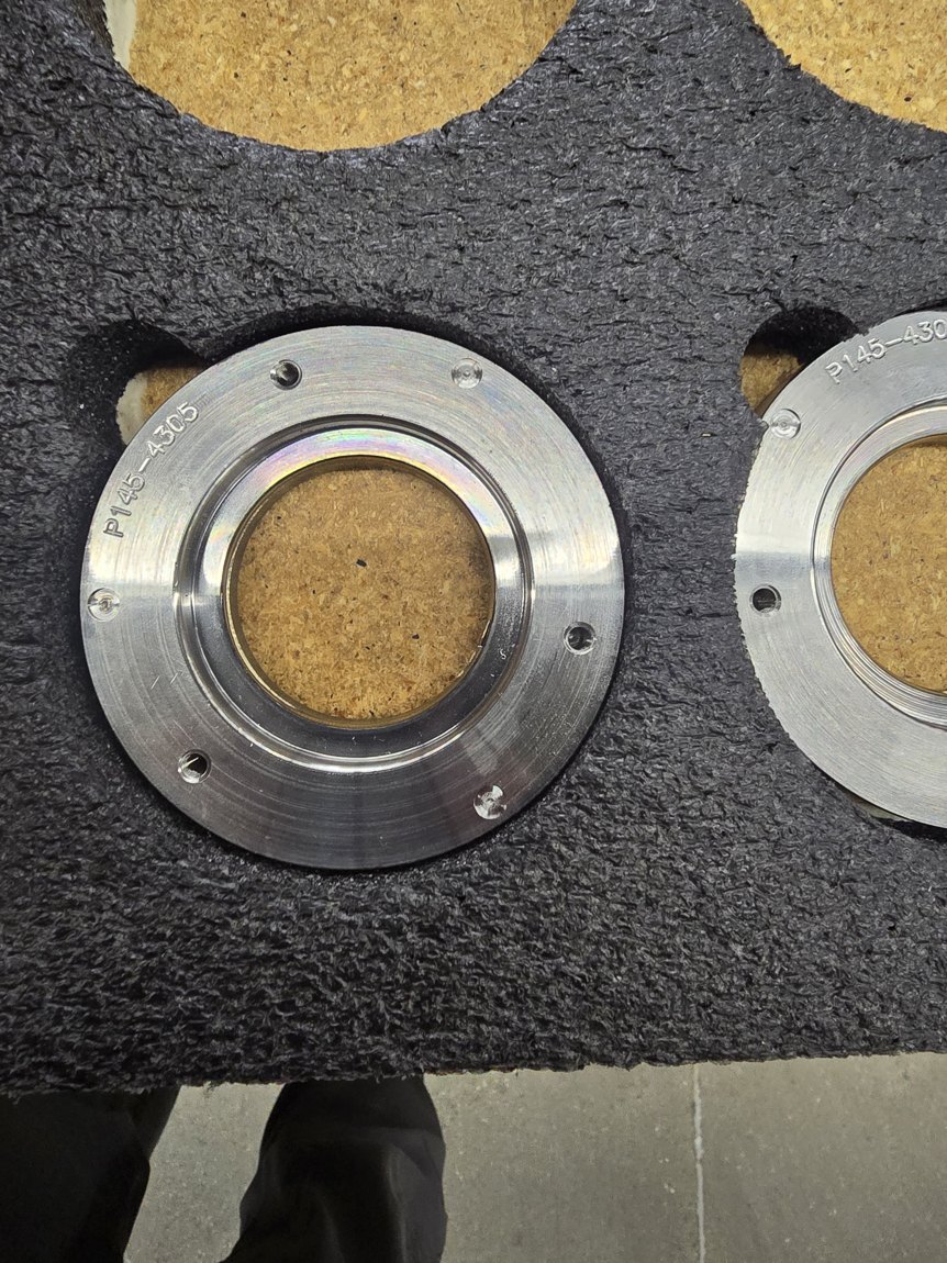
The part is a housing, magnet segments, and a pressed-on cover. 6/16 00:13:52“we take the mag plate and we put magnets in there and then they press these covers on” · 00:15:37“segments get put around here, and then this cover gets pressed on here.”The seam you weld is millimetres from those magnets, and their magnetism is the entire product. That is what the gas is protecting — not the weld.
20260616_131900 — the magnet segments, in the box marked …45-4027 · 20260616_131724 — finished mag plates, P145-4305
What the nitrogen is actually for
Not just shielding — cooling, and the reason is the product itself. Mike, 6/16 01:04:59: asked “is this to cool the part as it’s being welded?” he answers “Yep.” Then 01:05:09“Nitrogen is more money, but it’s colder. So we’re trying to keep heat out of… the magnets. It will take the magnets’ [magnetism] away… That’s why we don’t like re-welding them.” And 01:05:27: “That’s the secret sauce for precision torque. That’s how you keep that magnetism.”
There are TWO gas actions, and neither is start-up1 — the tank valve. His written step 6 says when, in his own capitals: TURN GAS ON AT TANK WHEN READY TO WELD.
2 — the flow check. On the HMI: Manual Operation → Gas #1 → ON, read Gas #1 Flow (ltr/min), then OFF again. 6/16 01:09:25“It’s always set, but I always like to double-check it” → 01:10:20“it’s at 30” → 01:10:50“I’m going to turn him back off.”Both belong to Module 11, Readiness. Neither happens here. And the readout is litres per minute, not psi — the machine’s own label. GAS PREASURE 30 on the setup sheet is shop shorthand for a flow reading.
The other half of the pair
The chiller went on at step 3 and has been drawing from this tank ever since — but the tank is still shut. Opening this valve is what actually delivers nitrogen. Chiller without tank, or tank without chiller, both give you nothing at the nozzle.
Why it earns a screen
It is the one step on the list whose correct execution is not doing it yet. A learner who works down the six steps in order and opens the tank has followed the list and still got it wrong. If this module ever does acquire a graded question, this is the one.
Recap composite — to author
11
Recap
#
Device
What it’s for
1
Laser main disconnect (rear)
powers the machine; slowest to wake
2
Fume extractor — rear switch and front button
pulls the weld plume off the part
3
Chiller
cools the laser
4
Operator panel — blue RESET, then All Home
clears E-stop, then finds machine zero
Closing line: gas at the tank when you’re ready to weld — not before.
Asset manifest
File
Screen
Note
20260706_095157.mp4 0.0–3.4s
1
clearest unobstructed work-envelope view in the project
20260706_094256.jpg
2
disconnect, off
20260706_094308.jpg
2
stepped in close, nameplate legible
20260706_094315.jpg
3
rear rocker, green I lit
20260706_094327.jpg
4
only BOFA front-panel frame in the project
20260706_094338.jpg
5
chiller disconnect, MSP 14/16/18
20260706_094846.jpg
6
operator column; key already at ON — use for the “not the key” callout
20260706_094850.jpg
6
E-stop banner up, HEAD NOT READY
20260706_094914.jpg
7
Machine is not homed.
20260706_094929.mp4 0–6s
7
finger on All Home
20260706_095027.jpg
7
homed, all green, axes at zero
20260706_095810.jpg
8
cylinder and regulator
20260706_095819.jpg
8
hand on the valve
20260616_131612.jpg
1, 9
the laminated procedure — also a Resource
Flagged as invention
Not evidence. Everything below is authored, and each item is here so it can be killed rather than absorbed.
The lateral step track. Not a real machine element — but its numbering is: six nodes, six lines on the laminated page. Replaced an earlier four-cell device-status strip, which was worse on two counts: the numbering was invented, and it rendered screens 5 and 6 identically because it had no state between “booting” and “ready”. Carried through the remaining modules per Tyler, 9 September — see the note below on where the binder and the course order diverge.
Screen 1’s framing line — “four separate machines, not all in the same place” — was mine, and is cut. Tyler, 2026-09-09: “I don’t recall him saying four separate machines need to be turned on… I would say different parts of the machine need to be switched on.” The course now says that instead.
The purpose statements. Mike states what to switch on, never why. Extractor pulls the plume off the optics; homing establishes axis zero. Standard machine facts, not his words.
Already caught, and struck. This screen previously read “the laser is water-cooled.” Invented, and wrong — Tyler corrected it on 9 September. The word chiller appears zero times across all four transcripts in every format; it exists only on the laminated page. The cooling the tape does describe is nitrogen, on the weld. Left here as evidence the flag list does its job. Now answered: the chiller draws nitrogen from the tank — Tyler, 9 September.
Open items
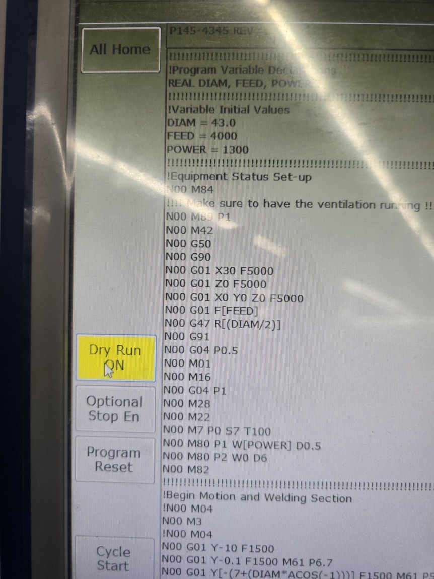
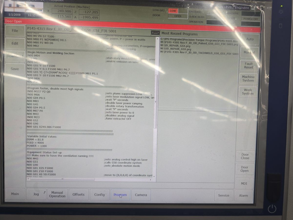
Assets are 7/06 but the spine job is P145-4305, a 6/16 job. Harmless here — nothing in this module is job-specific; a disconnect is a disconnect. Recorded so the mixed sourcing isn’t later read as a continuity error. Two 7/06 frames must not be used as-is elsewhere: the program pane behind the cold-start shots reads P145-4345 / DIAM 43.0, which contradicts the sheet and needs re-rendering.
The empty dry run stays out, since the module is procedural. It carries a real consequence — 00:47:08“it would hit the part and bump your nozzle” — and Mike ties it to start-up at 00:47:17“you only need to do that when you first start it up.” It needs a home. Recommend the dry-run module.
For Mike: does the setter check the revision letter, and what happens when only the older one is on the machine? On the 4315 job the machine held Rev C against paperwork saying REV D, and nobody remarked on it — so the mismatch is real even though it is not on the spine job.
For Mike: the pendant carries JOG − and JOG + buttons that appear in no session photograph and are mentioned nowhere in 167 minutes of tape.
Module 02
The Documents
The job arrives on paper carrying one number. You take that number to the Excel sheet to learn what to set up, and you take the same number to the machine to load the program that runs it. Two lookups, two computers — and knowing how to reach both is the module.
Assessed
Yes — one action
Screens
9
Shape
one number, two lookups
Graded on
Selecting the correct program
Spine
P145-4305 Rev F
The flow of the module
One number in, two lookups out. The job number off the order sheet is the key, and it opens two different things kept on two different computers. Read the Excel sheet to learn what the job needs; go to the machine to load the program that runs it.
off the order sheetP145-4305the job number
the setup sheetExcel · shop office PC
what your HANDS do
fixture · jaws · offsets* · ID/OD · gas · angle
* not a value you read and put down — a pair of registers you teach at the machine, and until you do they still hold the previous part’s positions
the weld program.prg · machine Touch Panel PC
what the MACHINE does
power · feed · diameters · weld order
but not where the part is — that lives in the offsets, not the program
The same number opens both, and neither one points at the other. The programs are filed under the job number too, so you never look one up from inside the other — you look up the same number twice, in two places.
Why open the Excel sheet at all — in Mike’s words
6/24 00:14:04 — asked what a setup sheet is: “Very basic information. The fixture they’re gonna use, how they’re gonna hang on.”6/16 00:23:28“…so it tells them their part number, tells them what fixture to use — and by fixture, that’s what you’re holding.”It is a physical setup document. What it tells you is what to pick up and bolt on — which is the whole of Modules 3 through 10.
And how the program is actually chosen
6/24 00:46:30“File — okay, file… and then you just pick the program. Your job number is right. So then you pick 4315, it’s highlighted.”By job number. The filenames start with the part number, so the order sheet alone gets you to the right file. The Excel sheet is how you confirm it — its OFFSET NUMBER and Fixture Number are printed in the filename too.
The one case where the Excel sheet really does choose the program — and it is this job
When a part has more than one program, the notes column is the only place that says so. None of the twelve fields carry it and nothing at the machine warns you. P145-4305 has three. That is why screen 5 exists.
What OFFSET NUMBER G50_G51 actually is — and why it is the sheet’s most important field
It is not a serial number and not a checksum. It names the two machine registers you will teach by hand during the dry run in Module 7.
6/16 00:50:10“You have two offsets that run the part. G50 does the ID and G51 does the OD.”6/16 00:37:22“Once you get it focused, choose your offset number and then you teach it… and then you teach that offset.”And the offsets are not in the program. 6/16 01:04:01: “Changing a program doesn’t change the offset… it’s going to go where you taught 50 and 51. I could bring three more programs over and have that offset — it’s going to go to that same spot.”So the fork has a third thing hanging off it: the program says what to do, the offsets say where, and the offsets are persistent machine state that the operator writes. The setup sheet is the only thing that tells you which pair to write.
Why the numbers are pre-assigned by family
6/16 00:52:54“That cover might go on five or six different magnets, so I try to use 50 and 51 for that cover, so that then it’s close for the guys — come in here and do this dry run and set their offsets. And then I might use 54, 55 for the next bigger cover, 56, 57 for the next big cover; I use 58, 59 for odd stuff… I always use G59 for the rotors.”Mike assigns a register pair per fixture family so the machine starts near the right place. That is why the pairs line up with the fixtures in the program library — FIX-5001→G50_G51, FIX-5003→G54_G55, FIX-5002→G56_G57 — and why the wrong-family picks on screen 8 are wrong in two ways at once.
#
Document
Where it lives
What you take from it
1
the order sheet
paper, green sleeve, on the bench
the job number — and nothing else
2
the setup sheet
Excel, on the shop office PC
fixture, jaws, offsets, ID/OD, gas, angle
3
the weld program
.prg, on the machine’s Touch Panel PC
power, feed, diameters, weld order
Two computers, one keyboard — why the lookups are not in one place
6/24 00:16:53, asked whether both are Excel files: “No, the program is actually in the machine.”6/24 00:49:13“These, they share a keyboard and mouse, right? So they switch back and forth.” · 00:49:25“This is this button switches the control of this to these… So now you’re on that computer.”Setup sheets are shop-office files. Programs live on the welder. Different systems, different owners — so the learner has to physically switch machines between the two halves of the fork.
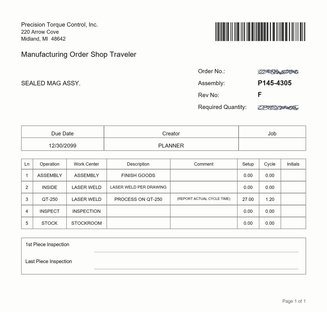
Naming — provisional, pending Mike“the order sheet” is Tyler’s recollection; the document is never named in 167 minutes and its printed title is Manufacturing Order Shop Traveler. Course rule: never say “sheet” alone — always the order sheet or the setup sheet, in full.
And the same trap with “plate”. Two different things carry the name: the mag plate is part of the workpiece — the machined housing the magnet segments sit in; the fixture plates are the three steel discs behind the fixture that those magnets grab. Tyler proposed the fix on tape and Mike took it — 6/24 00:28:25“what if we call them fixture plates?” — “We can do that… yeah.”Never say “plate” alone either.
Screen sequence
MOCK-UP — traced from the real travelers at 20260624_130334 / _130331 and 20260616_131731
01
The order sheet
The only thing you need from it is the assembly number. Everything about how to set up comes from the next document.
Assembly
P145-4305
what the setup sheet is filed under
Rev No
F
part of the number; never checked on tape
Order No. · Quantity
scribbled
for close-out, after this course ends
Routing
LASER WELD PER DRAWING
says the job comes here at all
What it does NOT carry
No fixture, no jaws, no offsets, no ID/OD, no power, feed, gas or rotary angle, and no program name. You cannot set the machine up from the order sheet.
20260624_130507 → 130515 → 130533 — photographed on the day
02
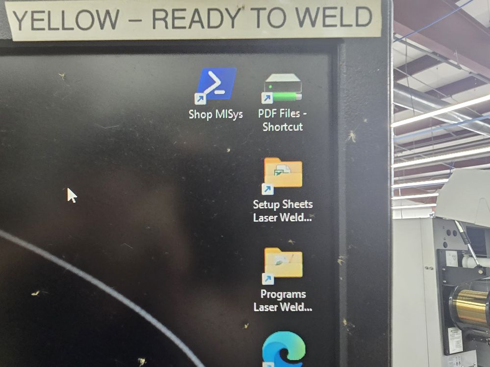
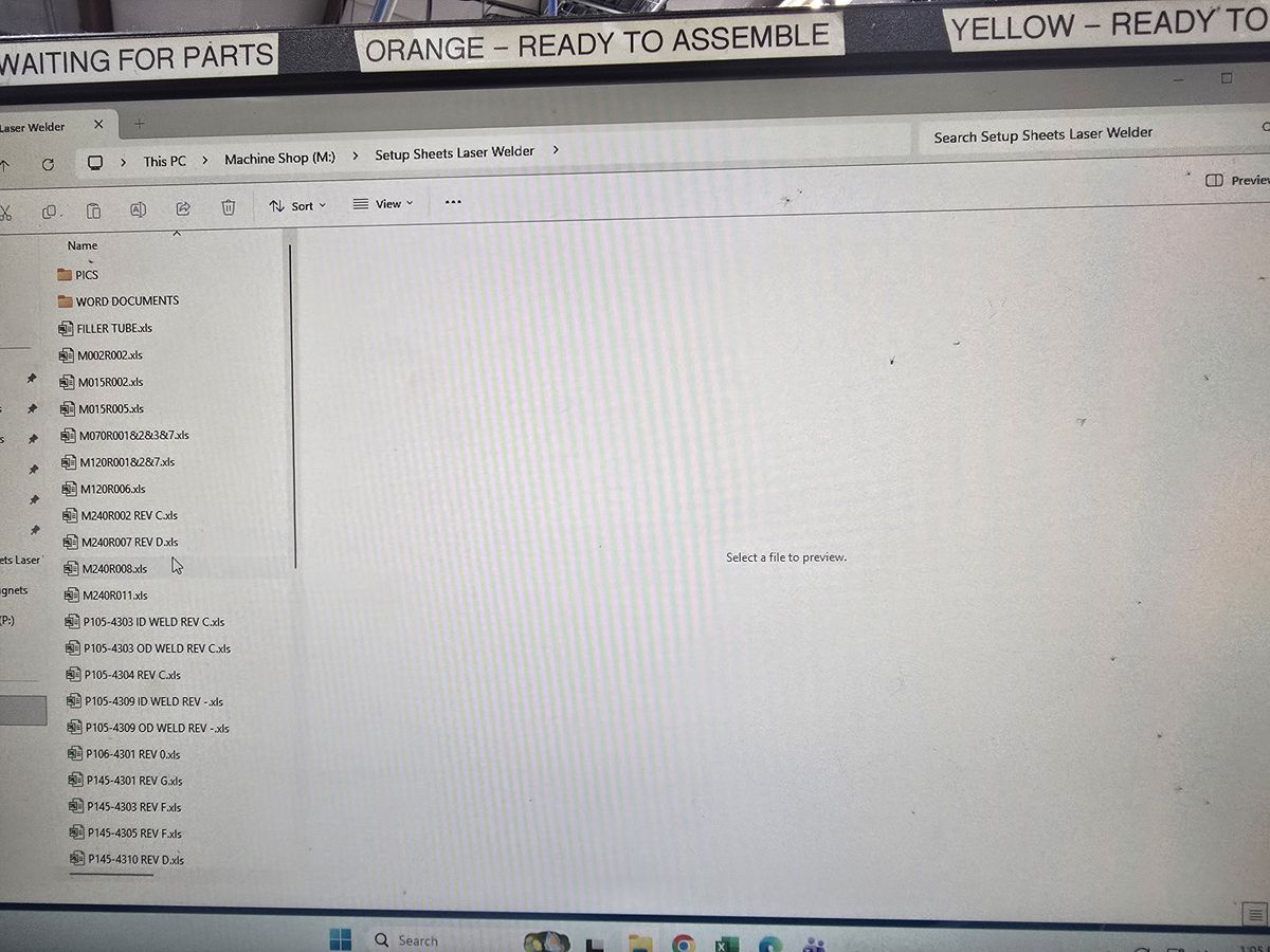
Finding the setup sheet CLICK PATH
On the shop office PC. You come here to find out what the job needs you to set up — fixture, jaws, offsets, sizes, gas, angle. Three clicks, each one a step the learner performs.
1
Desktop — double-click Setup Sheets Laser Weld…
130507
2
The folder opens — one workbook per part-rev
130515
3
Open P145-4305 REV F.xls
130533
Filed by part number
Which is why the order sheet came first. Also on this desktop: a Programs Laser Weld… shortcut and the laser schedule workbook — colour-coded rows with a Complete column, which you write to at the end, not read from now.
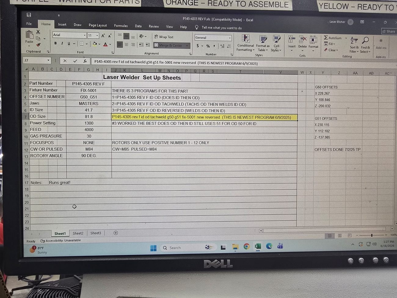
20260616_132708.jpg — the most complete setup-sheet capture in the project
03
The twelve values — the left branch
Part Number
P145-4305 REV F
Fixture Number
FIX-5001
OFFSET NUMBER
G50_G51
Jaws
MASTERS
ID / OD Size
41.7 / 81.8
Power · Feed · Gas
1300 / 4000 / 30
FOCUSPOS
NONE ROTORS ONLY
CW OR PULSED · ROTORY ANGLE
M84 / 90 DEG.
The rest of the sheet is the map of the course: OFFSET → M7 · Jaws → M3 · ID/OD → M7–8 · GAS → M10 · ROTORY ANGLE → M3. Power and Feed go nowhere — the program carries them. And FOCUSPOS reads NONE because it applies to rotors, which this course does not cover — the sheet says so itself.
Read G50_G51 as an instruction, not a labelG50 is the ID. G51 is the OD. Those are the two registers you will teach by hand during the dry run — you get the beam where you want it, go to offsets, choose the one you are teaching, and press set offset. This one field is the reason Module 7 exists.
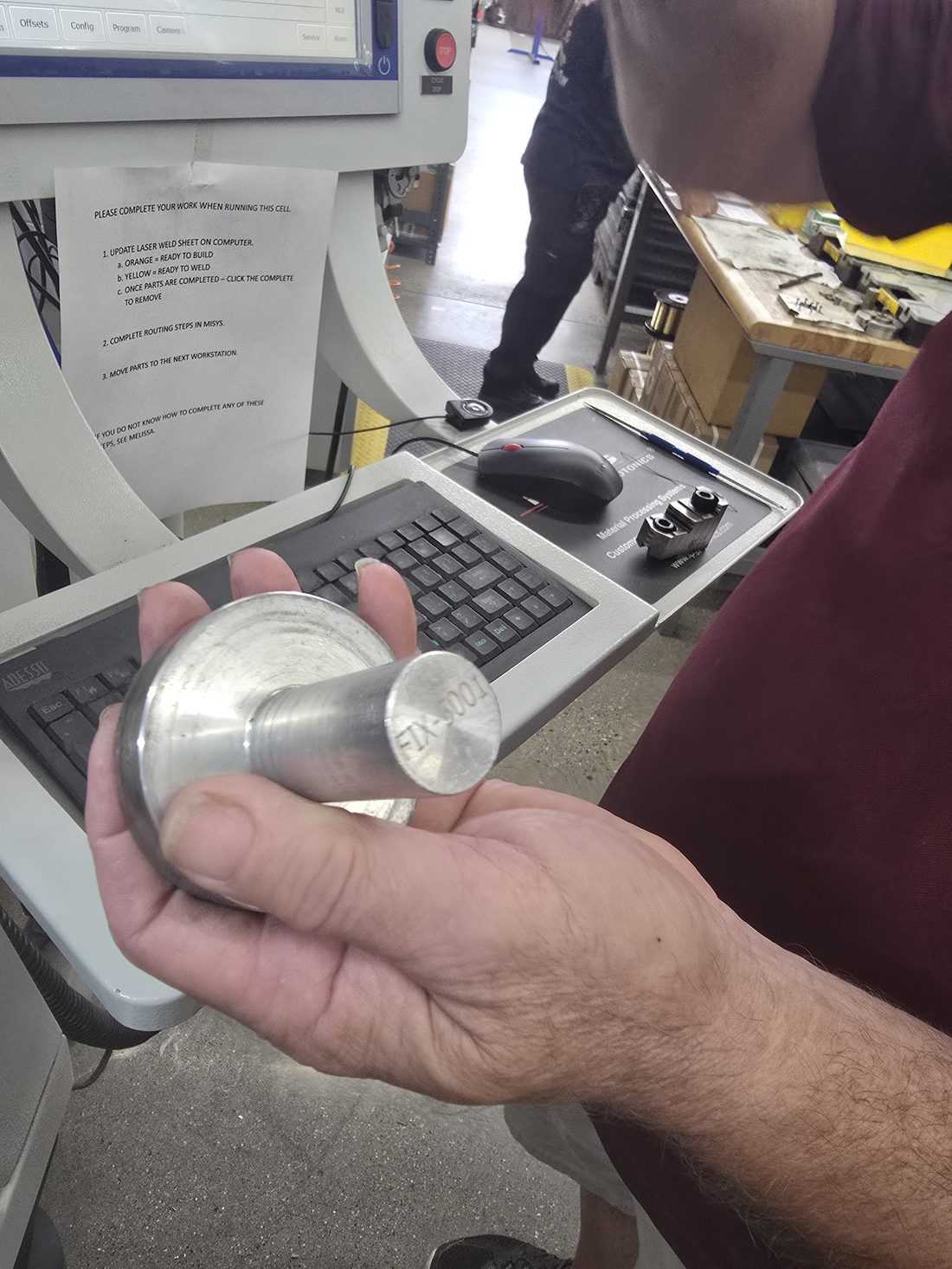
20260616_132716.jpg — FIX-5001 stamped on the end face
04
From the sheet to the object
The sheet says FIX-5001. Here it is in his hand with that number stamped into the end of the shank. Sheet to object in one move.
The fixture alone cannot identify a jobFIX-5001 serves most of the P145 family. Only the part number is unique.
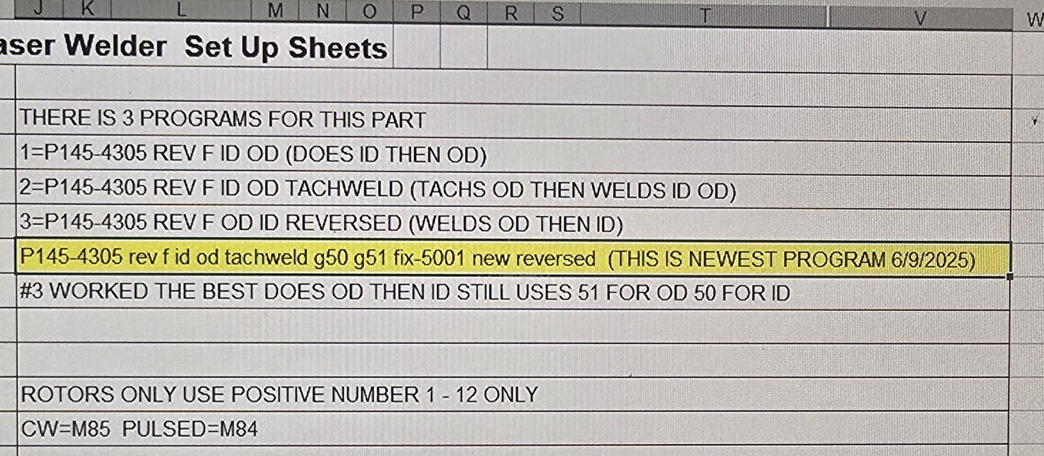
20260616_132708.jpg — the notes column, enlarged from the wide frame
05
Read the notes before you go to the machine
This is the one place the Excel sheet reaches across into the other branch. The twelve fields have no column that says a part has more than one program — only the notes do, and this part has three.
6/16 00:58:58“Normally we only ever have one program.”
6/16 01:01:21“So here’s the original, what we’ve always done… So that’s the one I want to try.”
A caution, not a judgment
Load the normal one — the plain ID_OD_Pulsed. If the notes recommend something different from what you are used to, stop and ask: the notes highlight one variant as “THIS IS NEWEST PROGRAM 6/9/2025” and separately say “#3 WORKED THE BEST”, and Mike loads neither.
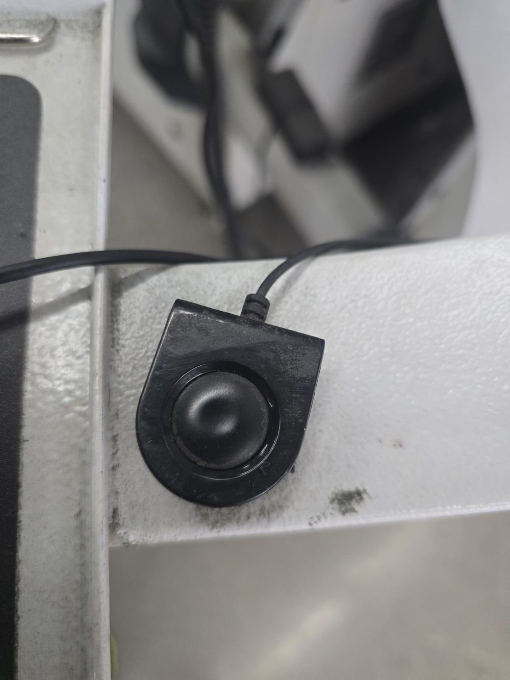
20260624_130423.jpg — candidate for the switch button; unlabelled, needs Mike to confirm
06
Switching to the machine
The setup sheet is on the shop office PC. The weld program is on the machine’s Touch Panel PC. One keyboard and mouse serve both, and a button switches between them.
6/24 00:49:13“These, they share a keyboard and mouse, right? So they switch back and forth.”
6/24 00:49:25“This is this button switches the control of this to these. … So now you’re on that computer.”
Open — which button
The action is narrated but the button is never pointed at on camera. 130423 shows an unlabelled corded pushbutton on the keyboard-shelf edge, photographed about a minute after that line — plausible but unconfirmed. Do not caption it until Mike says what it is.
20260624_130117 → 130128 → 130152 · same path on 6/16 at 140622
07
Finding the weld program CLICK PATH
On the machine’s Touch Panel PC — the right branch of the fork, reached by switching the keyboard. Three steps, all photographed.
1
Bottom tab strip — press Program
130117
2
Left rail — press File
130117
3
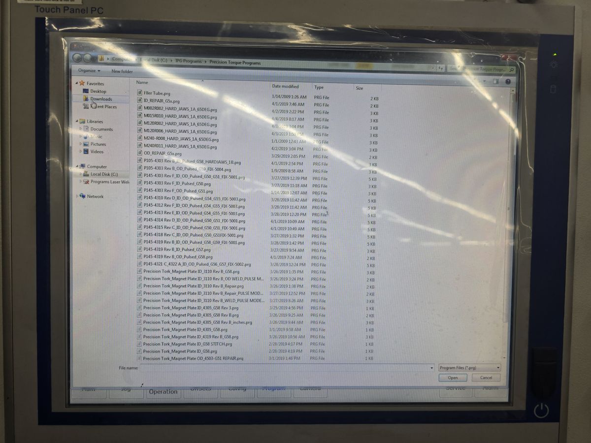
The Open dialog appears at C:\IPG Programs\Precision Torque Programs
130128 / 130152
Note the buttons for laterFile opens the dialog. Download is what sends the chosen program to the laser — picking it is not enough, and that is the next screen.
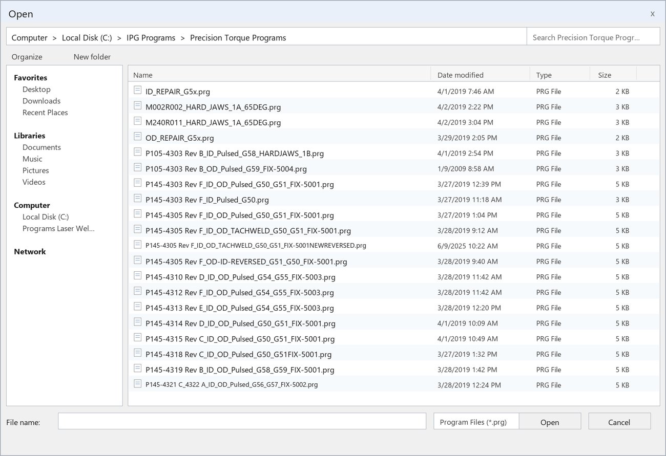
AUTHORED — filenames real, from the repo. No photograph shows a library containing 4305.
08
Pick it, then Download GRADED
SeesOrder sheet and setup sheet pinned left; the dialog live on the right.
DoesFinds the file by job number — selects P145-4305 Rev F_ID_OD_Pulsed_G50_G51_FIX-5001.prg, then Download.
ScoredThe right part number. Which variant is not graded. The setup sheet on the left is the check: its G50_G51 and FIX-5001 are printed in the filename.
If they pick
Feedback
4303 / 4314 / 4318
Right fixture and offsets, wrong part — most share FIX-5001 on G50_G51, which is why only the part number can be trusted.
4310 / 4312 / 4313
Wrong part and wrong fixture — FIX-5003 on G54_G55.
4319
Right family, wrong offsets — G58_G59.
ID / OD_REPAIR
Repair programs. Out of scope.
picks but skips Download
The machine still has the old program. Selecting is not loading.
What it costs
The machine does not check. Mike, 6/16 00:58:30: “Oh, somebody changed programs on me.”00:58:33“That’s alright, I’ll go get the one I want to do.” No alarm. He simply noticed.
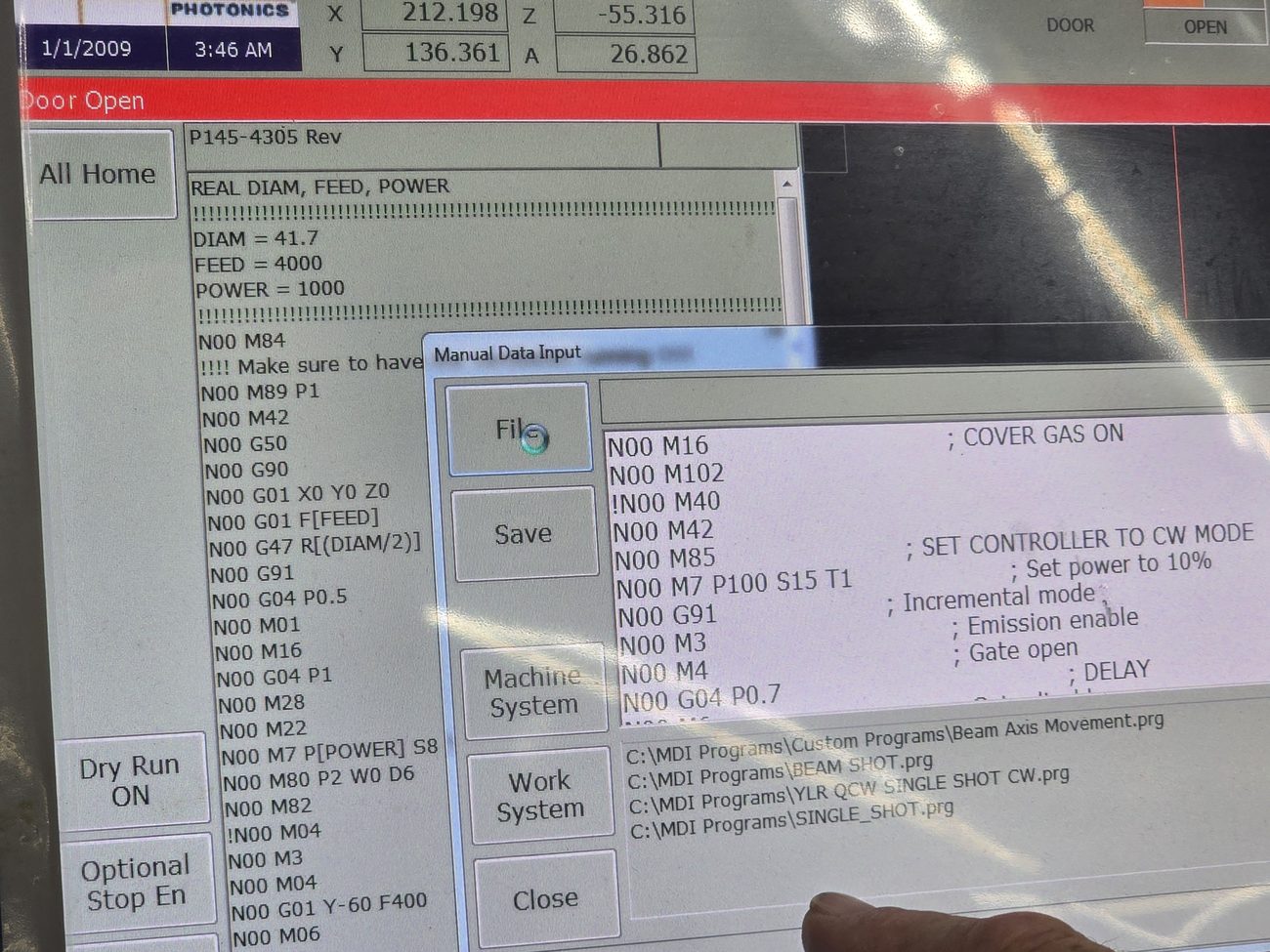
20260616_133929.jpg — clearest program-text capture in the corpus
09
It arrived with the numbers already in it
Field
Setup sheet
Weld program
ID Size / DIAM
41.7
DIAM = 41.7
FEED
4000
FEED = 4000
Power Setting
1300
POWER = 1300
Who states, and who commandsThe setup sheet STATES these values. The program COMMANDS them — everything except where each weld starts. Mike, 6/24 00:57:40: “But the program does that for you, right?” — “Yeah.” The learner reads and verifies; the learner does not type. That is Pitfall 3.
But it does NOT carry where the part is
The program commands power, feed, diameters and the weld order. Position is not in it. 6/16 01:04:01“Changing a program doesn’t change the offset… it’s going to go where you taught 50 and 51.” That is why OFFSET NUMBER is on the setup sheet and nowhere else, and why Module 7 is hands-on work rather than a lookup.
Power varies by block — not a fault1300 is the ID pass; the OD pass runs 1100, and tack-weld variants add a 1000 W block.
And the setup sheet can be missing
Mike, 6/24 00:16:28: “Set up sheets should be complete unless it’s a new job… or unless someone made a job and they didn’t make a set up sheet.”You do not proceed from the order sheet alone.
Flagged as invention — Module 2
Authored, not evidence. Kill any of these rather than let them settle.
The order sheet mock-up. Layout, routing, company block, Creator and Due Date traced from the real travelers; Assembly and Rev from the 4305 setup sheet. Order No., Quantity and the barcode are scribbled so they can never be mistaken for real data.
The program library screen. No photograph shows a library containing P145-4305 — 130152 runs 4303 → 4310 and skips it, because 4305’s programs live on an M: drive never browsed on camera. Every filename is real, from the repo’s export; neighbours and their dates transcribed from that photograph. Four modified-dates authored.
The switch-button photograph. The action is narrated; the button is not pointed at. 130423 is a candidate only.
“The order sheet” as a name — Tyler’s recollection, never spoken on tape.
“Stop and ask” on screen 5, and the per-distractor feedback wording on screen 8.
Open items — Module 2
Which button switches the computers? Narrated, never shown. Blocks captioning screen 6.
What is the green sleeve called? Blocks the vocabulary for all twelve modules.
Is the notes column stale, or is the habit stale? Screen 5 teaches the caution without the answer; the answer would let it teach the rule.
Does the revision letter do anything? Never checked on tape, and a Rev C / Rev D mismatch on the 4315 job was ignored in practice. Currently taught as part of the number, with no check attached.
Precision Tork · Laser Welder Setup TrainingStoryboard draft — 9 September 2026Spine job P145-4305 Rev F